
 prismo
Results#
All figures are from one run on the container mesh —
prismo run --use-containers --seed u --loss-weight 1e-5 --mesh-size 0.03 --r-min 0.1 --bias-sweep-points 6
(0.03 µm silicon elements, 0.1 µm filter radius, 556 design variables on
324 design cells), 192 MMA iterations in ~34 min on a laptop; outputs/ holds the PDFs of your own runs and
make figures refreshes docs/figures/ from them.
The U-shaped seed is the best of the three (lateral, vertical, u); the
seed comparison and the mesh study below give the evidence.
The gradient is validated before it is trusted#
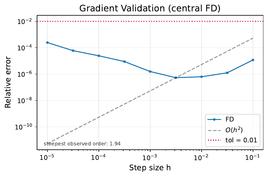
Composed adjoint vs central finite differences through filter → doping →
ChargeTransport (Julia, warm) → Soref–Bennett → gyptis, over nine steps from
\(10^{-1}\) down to \(10^{-5}\) (make validate-gradient-containers). The two
error branches of a difference quotient are both sampled, which is what makes
the curve a convergence test rather than a single number: above the minimum,
truncation dominates and the measured log-log slope is 1.94, the second
order a central difference should show; below it, the objective’s own
evaluation noise divided by the step takes over and the error climbs back as
\(\sim 1/h\). The best agreement is \(5.3\times10^{-7}\) at \(h \approx 3\times10^{-3}\),
four orders inside the \(10^{-2}\) gate.
The gradients do the work#
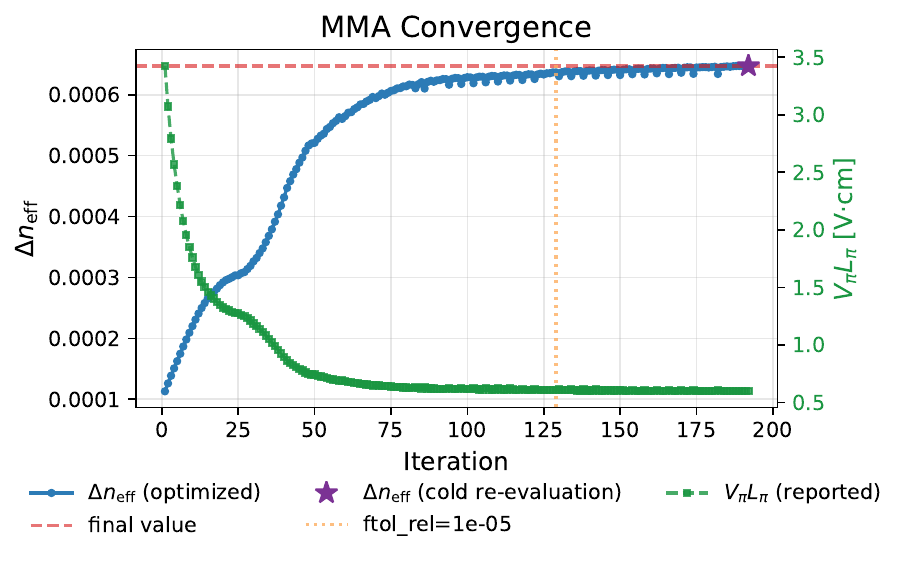
From the seeded U-shaped junction, MMA raises \(\Delta n_\mathrm{eff}\) at −5 V
from \(1.13\times10^{-4}\) to \(6.47\times10^{-4}\) (×5.7), i.e. \(V_\pi L_\pi\)
from 3.42 to 0.60 V·cm. Dips are rejected trials of the move-limited MMA,
kept in the record on purpose. (prismo run also re-solves the reported
design cold — worker reset, equilibrium from near-intrinsic, bias ramp — and
flags any warm/cold discrepancy, so the headline is a property of the design,
not of the solve path.)
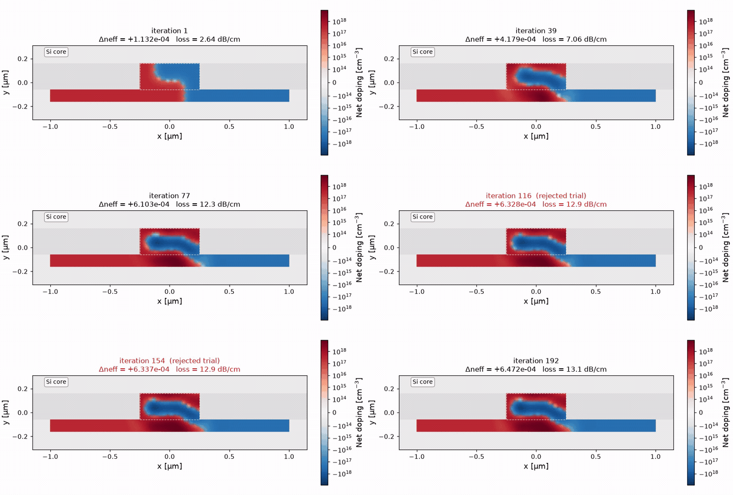
The net doping the two solvers saw at every evaluation: red n-type, blue p-type, white the junction. The optimizer drives the rib to the doping ceiling and closes the U seed into a ring: a p core enclosed by n on every side.
Before / after#
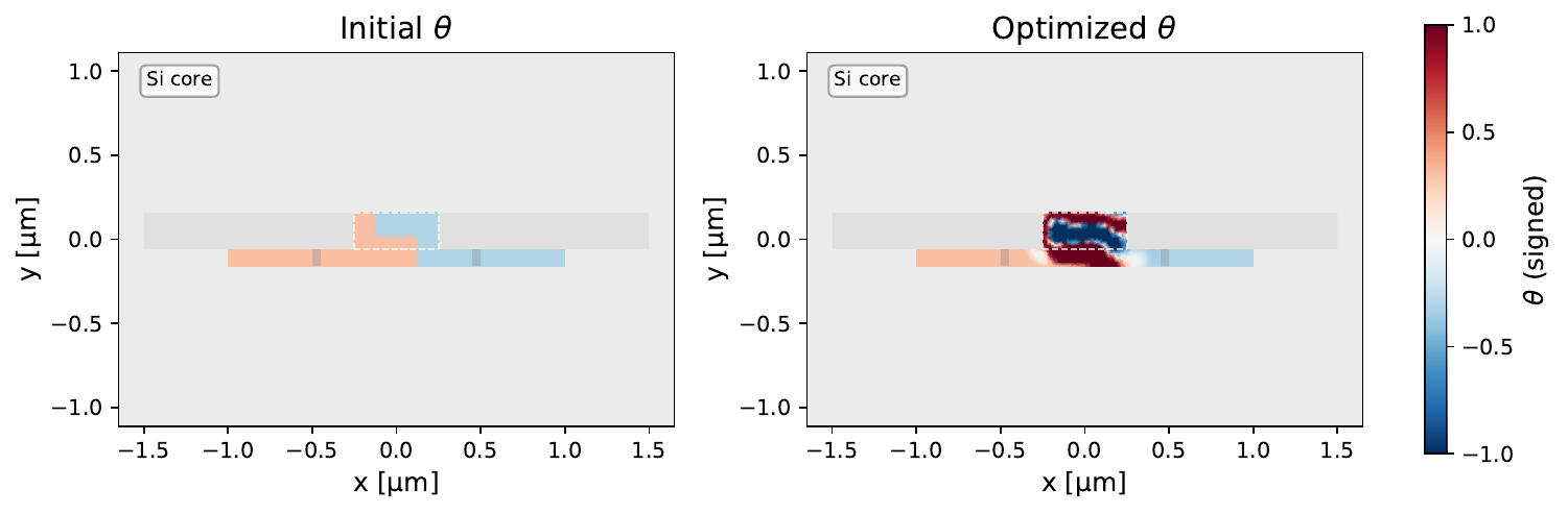
Left: the seed, a U-shaped junction at \(|N| \approx 3\times10^{17}\,\mathrm{cm^{-3}}\) — n wrapped under and beside a p core. Right: the optimum — the U has closed into a ring, a p core at the doping ceiling enclosed by n above, below and on both sides, with the junction sitting on the mode centre and the outer slab left at the seed where the mode does not reach. Closing the U is what buys the ×5.7 in \(\Delta n_\mathrm{eff}\): junction perimeter inside the mode is the currency, and a ring maximises it.
Where the modulation happens#
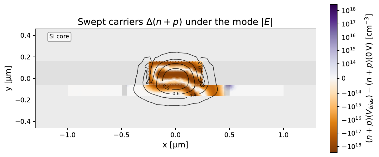
Carriers swept out between 0 V and −5 V at the optimum (orange, log scale), under the mode’s \(|E|\) contours. Depletion wraps the ring junction and fills the rib cross-section, covering the mode peak almost entirely — that overlap is the whole of the ×5.7. The pale band through the middle is the p core’s interior, too far from any junction to deplete; doping the mode cannot see would be loss for nothing, and the objective knows it: the outer slab is left alone.
The loss is watched, not ignored#
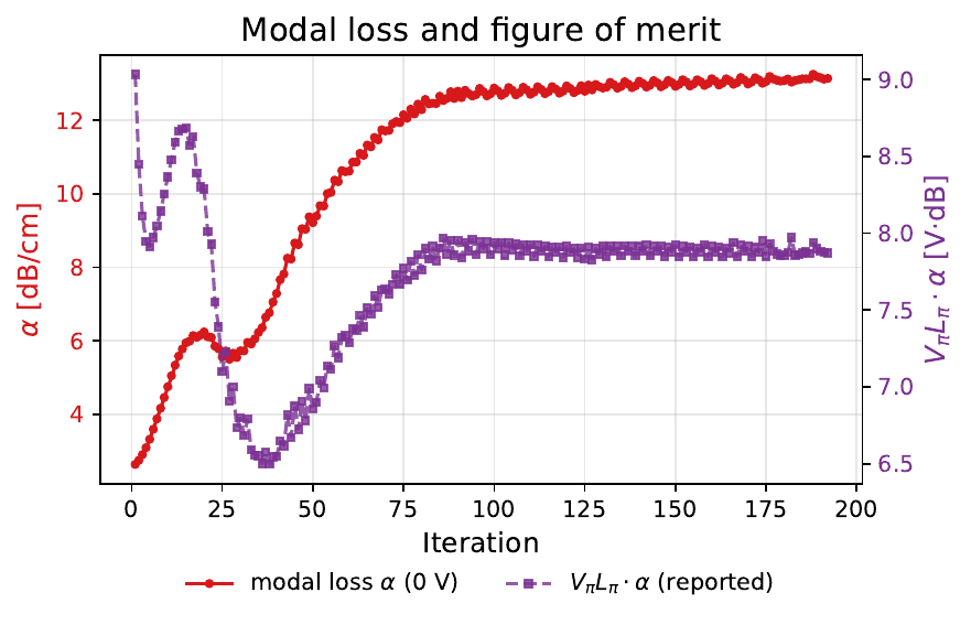
Modal free-carrier loss \(\alpha\) of the unbiased device and the efficiency–loss figure of merit \(V_\pi L_\pi\cdot\alpha\) at every iteration. The optimizer spends loss — 2.64 to 13.2 dB/cm — wherever it pays in \(\Delta n_\mathrm{eff}\), which rises faster, so the figure of merit still improves from 9.0 to 7.9 V·dB (good depletion modulators sit at 10–30 V·dB). At \(w = 10^{-5}\) the run travels along a near-constant \(V_\pi L_\pi\cdot\alpha\) line while \(V_\pi L_\pi\) falls fivefold: the weight, not the iteration count, is what moves the design across the trade-off.
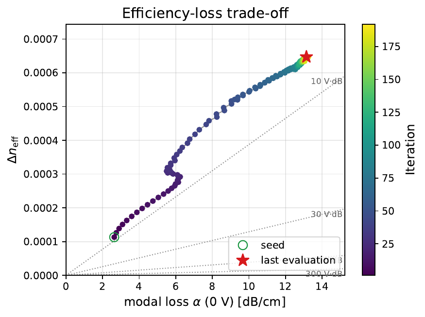
The same run as a path from seed to optimum in the \((\alpha, \Delta n_\mathrm{eff})\)
plane against iso-\(V_\pi L_\pi\cdot\alpha\) curves — the path tracks one of those
curves outwards. --loss-weight is what moves the optimum between them.
The seed picks the basin#
MMA finds a local optimum, so the starting topology matters. All three seeds
(--seed lateral|vertical|u) under identical settings on the 0.05 µm mesh,
192 iterations each:
seed |
\(\Delta n_\mathrm{eff}\) |
\(\alpha\) [dB/cm] |
\(V_\pi L_\pi\) [V·cm] |
\(V_\pi L_\pi\cdot\alpha\) [V·dB] |
|---|---|---|---|---|
|
\(6.21\times10^{-4}\) |
11.9 |
0.62 |
7.40 |
|
\(3.52\times10^{-4}\) |
6.34 |
1.10 |
6.98 |
|
\(3.74\times10^{-4}\) |
8.84 |
1.04 |
9.16 |
The U seed wins by 1.8× on efficiency at a figure of merit within 6% of the
best, which is why it is the default. The three land
1.8× apart from one another on \(V_\pi L_\pi\) — a spread larger than anything
the optimizer’s own settings (filter radius, move limit, iteration count) move,
so a multi-start is worth more than tuning the solver. The lateral run is also
the one whose cold re-solve failed, leaving its number warm-path-dependent;
u and vertical re-solved cold to the digit.
Mesh refinement#
The same U-seed run at three silicon element sizes, everything else identical (the filter radius is a physical length, so the minimum feature size is fixed at 0.1 µm across all three):
element size [µm] |
design cells |
\(\Delta n_\mathrm{eff}\) |
\(\alpha\) [dB/cm] |
\(V_\pi L_\pi\) [V·cm] |
\(V_\pi L_\pi\cdot\alpha\) [V·dB] |
|---|---|---|---|---|---|
0.05 |
116 |
\(6.21\times10^{-4}\) |
11.9 |
0.62 |
7.40 |
0.04 |
196 |
\(6.78\times10^{-4}\) |
14.2 |
0.57 |
8.10 |
0.03 |
324 |
\(6.47\times10^{-4}\) |
13.2 |
0.60 |
7.87 |
All three cold-re-solve to the digit and find the same ring topology, so the design is not a discretization artefact. The numbers, though, do not order with element size: \(V_\pi L_\pi\) spans 0.57–0.62 V·cm non-monotonically. That spread is not discretization error — it is which local optimum MMA settles into, and it is the honest uncertainty on the headline. The mode-overlap weights sum to 0.5717 / 0.5719 / 0.5718 across the three, so the optical side is converged; what changes is the design freedom (116 to 324 cells) and the path the optimizer takes through it.
The figures above are the 0.03 µm run — the finest mesh, and the smoothest picture of the same design.
Across the operating range#
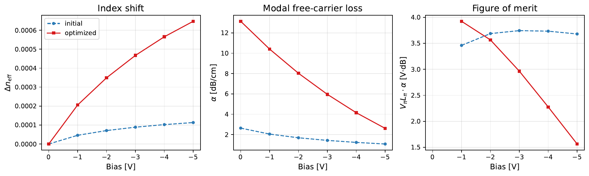
The reported figures of merit against reverse bias, seed and optimized design
side by side — a post-run characterization (--bias-sweep-points), not part of
the objective, which sees only the −5 V operating point.
\(\Delta n_\mathrm{eff}\) rises almost linearly to \(6.47\times10^{-4}\) and stays
4.5–5.7× the seed across the whole range, so the gain is not an artefact of the
one voltage it was optimized at. The loss panel reads \(\alpha\) from the carriers
at each bias rather than the objective’s fixed 0 V value, so it falls as the
junction empties — 13.2 dB/cm unbiased to 2.6 dB/cm at −5 V — while the lightly
doped seed, already mostly depleted, barely moves.
The product follows: \(V_\pi L_\pi\cdot\alpha\) improves from 3.92 V·dB at −1 V to 1.56 V·dB at −5 V, crossing below the seed just past −2 V. Above that the seed’s lighter doping still wins on the product — the design was optimized at −5 V and it shows. (These are bias-resolved \(\alpha\) values; the 7.9 V·dB headline above uses the objective’s 0 V loss, which is the pessimistic reading.)
The mode#
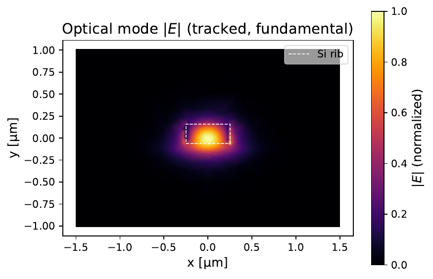
The tracked fundamental guided mode of the rib on the shared mesh
(--mode-index k targets a higher-order one).
Scope#
2D cross-section, one bias pair (0 / −5 V), first-order (overlap-weighted) loss on the rib cells only, Boltzmann statistics, no implant process model, and a headline carrying the ±5% local-optimum spread the mesh study measures — a prototype that points at the real device, not a tape-out.